Lesson 4: Digital I/O Basics
Understanding Digital Inputs and Outputs with Arduino
🎯 Learning Focus: Digital pins, LEDs, buttons, and basic control
📚 Learning Objectives
By the end of this Lesson, you will:
- ✓ Understand digital HIGH and LOW states
- ✓ Control LEDs with digitalWrite()
- ✓ Read button inputs with digitalRead()
- ✓ Implement pull-up and pull-down resistors
Key Concepts:
- • Digital pin modes (INPUT/OUTPUT)
- • Voltage levels (0V/5V)
- • Current limiting with resistors
- • Debouncing techniques
🔧 Section 1: Arduino IDE Setup & Hardware Connection
Installing the Arduino IDE
Now that you have your Arduino hardware, it's time to install the Arduino IDE (Integrated Development Environment) - the software we'll use to write and upload programs to your Arduino board.
What is the Arduino IDE?
- • Text Editor: Where you write your Arduino code (called "sketches")
- • Compiler: Translates your code into machine language
- • Uploader: Sends your compiled program to the Arduino board
- • Serial Monitor: View messages and data from your Arduino
- • Library Manager: Install additional code libraries for sensors and components
Installation Steps:
- Download: Go to
arduino.cc/softwareand download the Arduino IDE - Install: Run the installer and follow the setup wizard
- Connect: Plug your Arduino into your computer using the USB cable
- Select Board: Go to Tools → Board → Arduino Uno (or your specific board)
- Select Port: Go to Tools → Port → Select the COM port (Windows) or /dev/cu.usbmodem (Mac)
- Test: Upload the built-in "Blink" example to verify everything works
🔍 Troubleshooting Common Issues:
- • Port not found: Try different USB ports, restart the IDE, or install Arduino drivers
- • Upload failed: Check that the correct board and port are selected
- • Permission denied: Run Arduino IDE as administrator (Windows) or check permissions (Mac/Linux)
- • Board not recognized: Install CH340 drivers for clone Arduino boards
💡 Section 2: Digital Output Basics
Understanding Digital Signals
Digital signals have only two states: HIGH (5V) and LOW (0V). This binary nature makes them perfect for controlling devices like LEDs, motors, and relays.
Key Functions:
pinMode(pin, OUTPUT)- Configure pin as outputdigitalWrite(pin, HIGH)- Set pin to 5VdigitalWrite(pin, LOW)- Set pin to 0V
Basic LED Control
Let's start with the classic "Hello World" of electronics - blinking an LED.
Circuit Setup:
- • LED connected to digital pin 13
- • 220Ω resistor in series with LED
- • Ground connection to complete circuit
// Basic LED Blink Program
const int ledPin = 13;

void setup() {
  pinMode(ledPin, OUTPUT);
  Serial.begin(9600);
  Serial.println("LED Blink Program Started");
}

void loop() {
  digitalWrite(ledPin, HIGH);   // Turn LED on
  Serial.println("LED ON");
  delay(1000);                  // Wait 1 second

  digitalWrite(ledPin, LOW);    // Turn LED off
  Serial.println("LED OFF");
  delay(1000);                  // Wait 1 second
}
🔘 Section 2: Digital Input Basics
Reading Button States
Digital inputs allow us to read the state of switches, buttons, and sensors. The Arduino can detect whether a pin is HIGH or LOW.
Input Functions:
pinMode(pin, INPUT)- Configure pin as inputpinMode(pin, INPUT_PULLUP)- Input with internal pull-updigitalRead(pin)- Read pin state (HIGH/LOW)
Pull-up Resistors
Pull-up resistors ensure that input pins have a defined state when not connected to anything. Arduino has built-in pull-up resistors we can enable.
// Button Input with Pull-up Resistor
const int buttonPin = 2;
const int ledPin = 13;

void setup() {
  pinMode(buttonPin, INPUT_PULLUP);  // Enable internal pull-up
  pinMode(ledPin, OUTPUT);
  Serial.begin(9600);
  Serial.println("Button Input Program Started");
}

void loop() {
  int buttonState = digitalRead(buttonPin);

  if (buttonState == LOW) {  // Button pressed (pull-up inverts logic)
    digitalWrite(ledPin, HIGH);
    Serial.println("Button Pressed - LED ON");
  } else {
    digitalWrite(ledPin, LOW);
    Serial.println("Button Released - LED OFF");
  }

  delay(50);  // Debounce delay
}
🔄 Section 3: Combining Input and Output
🔧 Introduction to Breadboards
A breadboard is a reusable platform for building electronic circuits without soldering. It makes connecting components to your Arduino much easier!
How Breadboards Work:
- Rows: Each numbered row (1-30) has 5 connected holes on each side
- Power Rails: The long strips marked + and - run the full length
- Center Gap: Separates left and right sides of each row
- No Connection: Holes in different rows are not connected
Breadboard Setup Tips:
- Connect Arduino 5V to the + power rail (red stripe)
- Connect Arduino GND to the - power rail (blue/black stripe)
- Use jumper wires to connect components to Arduino pins
- Keep wires neat and use different colors for organization
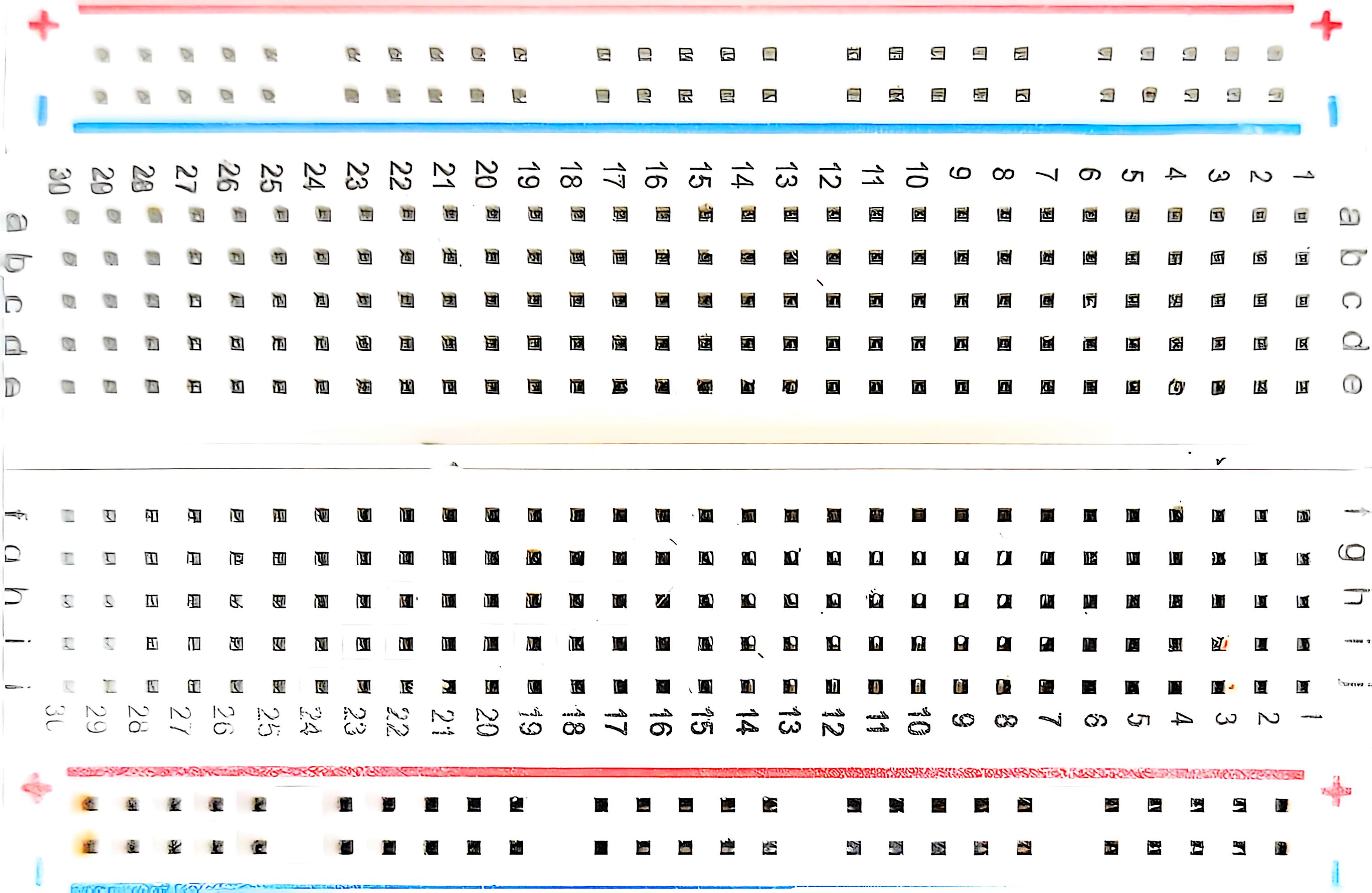
Clean breadboard ready for components
🔌 Push Button Wiring with Breadboard
Step-by-Step Wiring:
- Set up power rails: Connect Arduino 5V to breadboard + rail, GND to - rail
- Place push button: Insert button across the center gap (e.g., rows 10-12)
- Connect to pin 2: Wire from Arduino digital pin 2 to one side of button
- Connect to ground: Wire from other side of button to - power rail (GND)
- No resistor needed: The code uses INPUT_PULLUP mode
💡 Why INPUT_PULLUP works: This mode connects an internal 20kΩ resistor between the pin and 5V. When the button is pressed, it connects the pin to ground (LOW). When released, the pull-up resistor keeps the pin at 5V (HIGH).
Note: The built-in button on the expansion board is connected to reset, not pin 2, so we need an external button for this exercise.

Push button connected to pin 2 with breadboard wiring
Interactive LED Control
Now let's create more interactive programs that respond to user input and control multiple outputs.
// Toggle LED with Button Press
const int buttonPin = 2;
const int ledPin = 13;

bool ledState = false;
bool lastButtonState = HIGH;
bool currentButtonState = HIGH;

void setup() {
  pinMode(buttonPin, INPUT_PULLUP);
  pinMode(ledPin, OUTPUT);
  Serial.begin(9600);
  Serial.println("LED Toggle Program Started");
}

void loop() {
  currentButtonState = digitalRead(buttonPin);

  // Check for button press (HIGH to LOW transition)
  if (lastButtonState == HIGH && currentButtonState == LOW) {
    ledState = !ledState;  // Toggle LED state
    digitalWrite(ledPin, ledState);

    if (ledState) {
      Serial.println("LED Toggled ON");
    } else {
      Serial.println("LED Toggled OFF");
    }

    delay(50);  // Simple debounce
  }

  lastButtonState = currentButtonState;
}
Multiple LEDs and Patterns
Let's create more complex patterns using multiple LEDs and timing.
🔌 Multiple LED Wiring with Breadboard
Traffic Light LED Setup:
- Red LED: Long leg → 220Ω resistor → Arduino pin 11, Short leg → GND rail
- Yellow LED: Long leg → 220Ω resistor → Arduino pin 12, Short leg → GND rail
- Green LED: Long leg → 220Ω resistor → Arduino pin 13, Short leg → GND rail
- Push button: One side → Arduino pin 2, Other side → GND rail
- Power rails: Connect Arduino GND to breadboard - rail
💡 LED Polarity: LEDs have polarity - the long leg (anode) connects to the positive side through a resistor, and the short leg (cathode) connects to ground.
⚡ Why 220Ω resistors: These limit current to protect the LEDs from burning out. Each LED needs its own resistor.
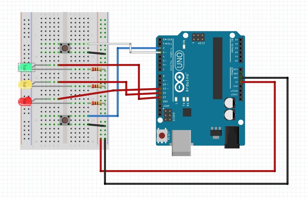
Traffic light LEDs with control buttons - complete interactive setup
// Traffic Light Simulator
const int redPin = 11;
const int yellowPin = 12;
const int greenPin = 13;
const int buttonPin = 2;

void setup() {
  pinMode(redPin, OUTPUT);
  pinMode(yellowPin, OUTPUT);
  pinMode(greenPin, OUTPUT);
  pinMode(buttonPin, INPUT_PULLUP);
  Serial.begin(9600);
  Serial.println("Traffic Light Simulator Started");
}

void loop() {
  // Green light
  digitalWrite(greenPin, HIGH);
  digitalWrite(yellowPin, LOW);
  digitalWrite(redPin, LOW);
  Serial.println("GREEN - Go!");
  delay(3000);

  // Yellow light
  digitalWrite(greenPin, LOW);
  digitalWrite(yellowPin, HIGH);
  digitalWrite(redPin, LOW);
  Serial.println("YELLOW - Caution!");
  delay(1000);

  // Red light
  digitalWrite(greenPin, LOW);
  digitalWrite(yellowPin, LOW);
  digitalWrite(redPin, HIGH);
  Serial.println("RED - Stop!");
  delay(3000);
}
🛠️ Hands-On Activity: Interactive Control Panel
Project: Build a Simple Control Panel
Create an interactive control panel with multiple buttons and LEDs that demonstrates digital I/O concepts.
Required Components:
- • Arduino Uno
- • 3 LEDs (Red, Yellow, Green)
- • 2 Push buttons
- • 3 × 220Ω resistors (for LEDs)
- • Breadboard and jumper wires
Challenge Tasks:
- Wire the circuit according to the schematic
- Program button 1 to cycle through LED colors
- Program button 2 to create a blinking pattern
- Add Serial Monitor feedback for all actions
- Implement proper button debouncing
// Control Panel Challenge Solution
const int redPin = 11;
const int yellowPin = 12;
const int greenPin = 13;
const int button1Pin = 2;
const int button2Pin = 3;

int currentLED = 0;  // 0=red, 1=yellow, 2=green
bool blinkMode = false;
bool lastButton1State = HIGH;
bool lastButton2State = HIGH;

void setup() {
  pinMode(redPin, OUTPUT);
  pinMode(yellowPin, OUTPUT);
  pinMode(greenPin, OUTPUT);
  pinMode(button1Pin, INPUT_PULLUP);
  pinMode(button2Pin, INPUT_PULLUP);
  Serial.begin(9600);
  Serial.println("Control Panel Ready!");
}

void loop() {
  // Check button 1 for LED cycling
  bool button1State = digitalRead(button1Pin);
  if (lastButton1State == HIGH && button1State == LOW) {
    currentLED = (currentLED + 1) % 3;
    Serial.print("Switched to LED: ");
    Serial.println(currentLED);
    delay(50);  // Debounce
  }
  lastButton1State = button1State;

  // Check button 2 for blink mode
  bool button2State = digitalRead(button2Pin);
  if (lastButton2State == HIGH && button2State == LOW) {
    blinkMode = !blinkMode;
    Serial.print("Blink mode: ");
    Serial.println(blinkMode ? "ON" : "OFF");
    delay(50);  // Debounce
  }
  lastButton2State = button2State;

  // Control LEDs
  updateLEDs();
}

void updateLEDs() {
  // Turn off all LEDs first
  digitalWrite(redPin, LOW);
  digitalWrite(yellowPin, LOW);
  digitalWrite(greenPin, LOW);

  // Turn on current LED
  if (blinkMode && (millis() % 500 < 250)) {
    // Blink current LED
    switch(currentLED) {
      case 0: digitalWrite(redPin, HIGH); break;
      case 1: digitalWrite(yellowPin, HIGH); break;
      case 2: digitalWrite(greenPin, HIGH); break;
    }
  } else if (!blinkMode) {
    // Solid current LED
    switch(currentLED) {
      case 0: digitalWrite(redPin, HIGH); break;
      case 1: digitalWrite(yellowPin, HIGH); break;
      case 2: digitalWrite(greenPin, HIGH); break;
    }
  }
}
📝 Assessment & Homework
📊 Lesson 4 Quiz Topics:
- • Digital HIGH and LOW states
- • pinMode() configurations
- • digitalWrite() and digitalRead()
- • Pull-up resistor concepts
- • Button debouncing techniques
🏠 Homework Assignments:
- 1. Complete the control panel project
- 2. Create a binary counter with 4 LEDs
- 3. Design a simple alarm system
- 4. Research different types of switches
- 5. Practice circuit diagrams and schematics
💡 Pro Tips for Success:
- • Always check your wiring before powering on
- • Use the Serial Monitor to debug your programs
- • Start with simple circuits and add complexity gradually
- • Keep a notebook of working circuit configurations