Lesson 6: PWM & Analog Outputs
Master Pulse Width Modulation and analog output control
🎛️ Learn to control brightness, speed, and analog devices
📚 Learning Objectives
By the end of this lesson, you will:
- • Understand PWM (Pulse Width Modulation) principles
- • Use analogWrite() for analog output control
- • Control LED brightness and motor speed
- • Create smooth fading and dimming effects
Key Concepts:
- • PWM frequency and duty cycle
- • Arduino PWM pins and limitations
- • RGB LED color mixing
- • Servo motor control basics
🌊 Section 1: Understanding PWM
What is PWM?
Pulse Width Modulation (PWM) is a technique used to simulate analog output using digital signals. Instead of providing a continuous voltage like true analog output, PWM rapidly switches between HIGH (5V) and LOW (0V) states.
Key PWM Concepts:
- Duty Cycle: Percentage of time the signal is HIGH
- Frequency: How fast the switching occurs (typically 490Hz or 980Hz)
- Average Voltage: Effective voltage based on duty cycle
PWM on Arduino
Arduino Uno has 6 PWM-capable pins: 3, 5, 6, 9, 10, and 11 (marked with ~ symbol). These pins can output PWM signals with values from 0 (0% duty cycle) to 255 (100% duty cycle).
PWM Value Examples:
- 0: Always LOW (0V average)
- 64: 25% duty cycle (1.25V average)
- 128: 50% duty cycle (2.5V average)
- 192: 75% duty cycle (3.75V average)
- 255: Always HIGH (5V average)
⚡ Section 2: analogWrite() Function
Basic analogWrite() Syntax
The analogWrite() function generates PWM signals on compatible pins. It takes two parameters: the pin number and the PWM value (0-255).
analogWrite() Syntax:
analogWrite(pinNumber, pwmValue) Generates PWM signal on specified pin (0-255 range)
PWM Value Examples:
- • 0 = LED off (0% brightness)
- • 64 = LED dim (25% brightness)
- • 128 = LED medium (50% brightness)
- • 255 = LED full brightness (100%)
LED Brightness Control
One of the most common uses of PWM is controlling LED brightness. Here's a complete example that gradually fades an LED in and out:
Wiring Diagram
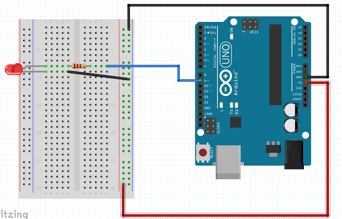
Wiring: Connect the LED's long leg (anode) to pin 9 through a 220Ω resistor, and the short leg (cathode) to GND.
// LED Fading Example
const int ledPin = 9;  // PWM pin
int brightness = 0;    // LED brightness
int fadeAmount = 5;    // How much to change brightness

void setup() {
  Serial.begin(9600);
}

void loop() {
  // Set LED brightness
  analogWrite(ledPin, brightness);

  // Print current brightness
  Serial.print("Brightness: ");
  Serial.println(brightness);

  // Change brightness for next iteration
  brightness = brightness + fadeAmount;

  // Reverse direction at the ends
  if (brightness <= 0 || brightness >= 255) {
    fadeAmount = -fadeAmount;
  }

  delay(30);  // Small delay for smooth fading
}
Color Mixing with PWM
RGB LEDs contain three separate LEDs (Red, Green, Blue) that can be controlled independently using PWM. By mixing different intensities of these colors, you can create millions of colors.
Common RGB Colors:
- Red: (255, 0, 0)
- Green: (0, 255, 0)
- Blue: (0, 0, 255)
- White: (255, 255, 255)
- Purple: (255, 0, 255)
- Yellow: (255, 255, 0)
- Cyan: (0, 255, 255)
RGB LED Control Code
🔌 RGB LED Wiring Instructions
Before running the RGB LED code, you need to connect an RGB LED properly:
Common Cathode RGB LED Wiring:
- Red pin → 220Ω resistor → Digital pin 9
- Green pin → 220Ω resistor → Digital pin 10
- Blue pin → 220Ω resistor → Digital pin 11
- Common cathode (longest pin) → GND
Alternative: Use Built-in RGB LED
If your expansion board has a built-in RGB LED, check its pin connections and modify the pin numbers in the code accordingly.
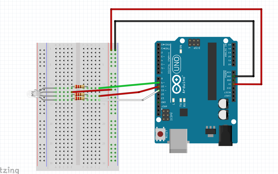
RGB LED Wiring: Red → Pin 9, Green → Pin 10, Blue → Pin 11 (each with 220Ω resistor)
Here's an example that cycles through different colors on an RGB LED:
// RGB LED Color Cycling
const int redPin = 9;    // Red LED pin
const int greenPin = 10; // Green LED pin
const int bluePin = 11;  // Blue LED pin

void setup() {
  Serial.begin(9600);
  Serial.println("RGB LED Color Demo");
}

void loop() {
  // Red
  setColor(255, 0, 0);
  Serial.println("Red");
  delay(1000);

  // Green
  setColor(0, 255, 0);
  Serial.println("Green");
  delay(1000);

  // Blue
  setColor(0, 0, 255);
  Serial.println("Blue");
  delay(1000);

  // Purple
  setColor(255, 0, 255);
  Serial.println("Purple");
  delay(1000);

  // Off
  setColor(0, 0, 0);
  Serial.println("Off");
  delay(1000);
}

// Function to set RGB color
void setColor(int red, int green, int blue) {
  analogWrite(redPin, red);
  analogWrite(greenPin, green);
  analogWrite(bluePin, blue);
}
🛠️ Hands-On Activity: PWM Control Panel
Project: Interactive PWM Demonstration
Create a program that demonstrates PWM control using the Serial Monitor as a control interface. This kit-independent activity will help you understand PWM principles through simulation and code.
Activity Instructions
- Create a PWM control program with Serial Monitor interface
- Include commands for LED brightness (L0-L255)
- Add motor speed control simulation (M0-M255)
- Implement RGB color control (R/G/B commands)
- Test different PWM values and observe the effects
- Create a demo mode that cycles through different settings
📝 Assessment & Homework
Quick Check Questions
- What PWM value would give you 75% brightness on an LED?
- Which Arduino pins support PWM output?
- What RGB values would create a yellow color?
- Why can't you connect a motor directly to an Arduino pin?
- What is the frequency range of Arduino PWM signals?